General, quoting & support.
Add: Building E, No.58, Nanchang Road, Xixiang , Baoan District Shenzhen City, Guangdong, China
Tel : 0755-27348887
Fax : 0755-27349876
E-mail : svc@pcbastore.com
An Overview of Circuit Board Diodes
Simon / 2021-05-15
Contents [hide]
Do you wish to know all about circuit board diodes? Are you struggling to find out relevant information about PCB diodes? You have hit the right spot. This article will answer all your diodes-related queries and give you a detailed overview of its various types, applications along with how it is tested. So, what are you waiting for? Read along and find out all you need to know about diodes.

What are diodes in the circuit board?
Diodes are one of the simplest semiconductor components. A diode can perform a range of important functions. Its main ability lies in determining the direction of electrical current. Diodes permit current to pass through them only in one direction.
The ability to guide the flow of current only in the proper direction is achieved with the help of a built-in electric field. Though in the earlier days, diodes were made up of red-hot wires, diodes that are in use today are semiconductor diodes. These are manufactured from semiconductor materials, specially doped silicon.
What are the application areas of circuit board diodes?
Power conversion
Diodes can change AC power to DC power. One diode or a group of 4 diodes can convert household power of 110V to DC by constructing a full-wave or a halfway rectifier. Just � of the AC waveform can pass through it. As a capacitor gets charged by this voltage pulse, the output voltage becomes a steady DC voltage having a minimum voltage ripple.
You can make a half-wave rectifier just by using a single diode. If you send an AC signal through a diode, all negative components will be clipped out.
A full-wave rectifier needs four diodes for converting the negative components in the AC signal into positive components.
Signal demodulation
PCB diodes are most commonly used to eliminate an AC signal's negative component. Since the AC waveform's negative portion is generally similar to the positive half, not much information is lost in the stripping process. This leads to better processing of the signal. Signal demodulation is normally used in radios for successful extraction of the radio signal.
Logic gates
The computing binary trees are constructed on logic gates. Enabled by diodes, these gates regulate if a switch is off ("0") or on ("1"). In modern processors, one can find millions of diodes in operation.
Voltage spike suppression
Diodes are very commonly used to restrict potential damage from unexpected large voltage spikes. TVS or transient voltage suppression diodes, just like Zener diodes, have lowish breakdown voltages and high power ratings. These diodes are specially designed so that they can absorb energy if voltages go beyond their breakdown voltage.
Current steering
Diodes are also commonly applied to steer current. They also are used to make sure that the current flows only in the proper direction. The diodes' current steering ability is greatly used in switching the power from a power supply to power run by battery.
Suppose your cellphone is plugged in and charging. Now, the phone should draw power just from the external power source. Also, when the cell phone is plugged in, it is only the battery that shall draw power and recharge itself. Once you remove the power source, the battery shall be able to power the device.
Reverse current protection
Have you ever incorrectly placed a battery? Have you ever got confused with the black and red power wires? If this has ever occurred, then it is a diode for which your circuit is still alive. When you place a diode in series with the power supply's positive side, it is known as a reverse protection diode. This makes sure that the power supply applies only a positive voltage and current flows only in the positive direction.
However, the reverse protection diode comes with a disadvantage. It often leads to some amount of voltage loss due to the forward voltage drop. Therefore, in the case of reverse protection diode, Schottky diodes are a good choice.
What are the different types of diodes?
There are a variety of circuit board diodes available in the market. Some of them are as follows:
Signal diodes
These are the usual, average, and most basic diodes. These diodes normally have a medium to high forward drop in the voltage along with a rating of low maximum current. One of the most common examples of such a diode is 1N4148.
Power diodes
A power diode, also known as a rectifier, is a standard diode having a current rating that is of a much higher maximum. The higher current rating is generally obtained in exchange for a larger forward voltage. A classic power diode example is 1N4001.
Light-emitting diodes
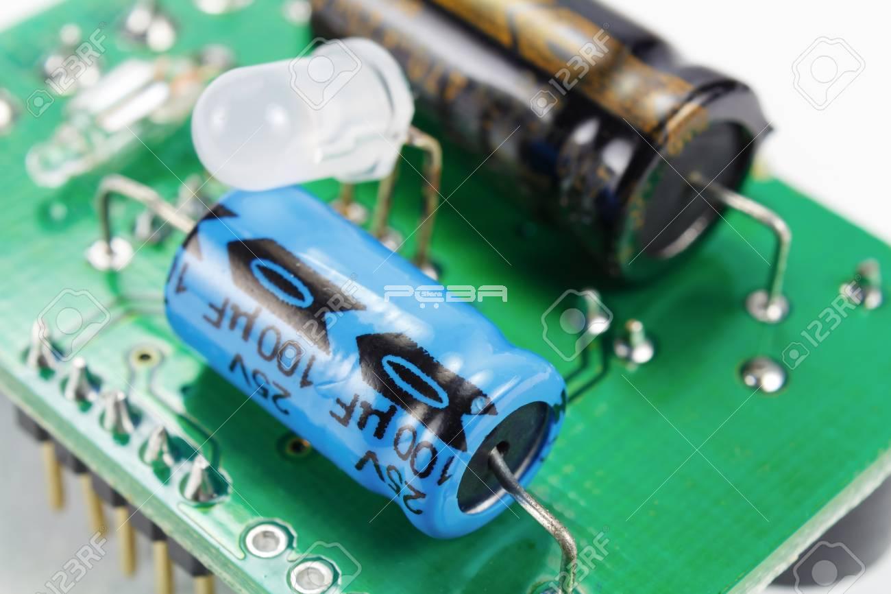
Among the different diodes in the diode family, the light-emitting diode or LED is the flashiest member. These diodes normally light up whenever they receive a positive voltage. LED PCB diodes allow current just through a single direction. Generally, an LED diode's VF rating is larger when compared to a normal, usual diode (1.2~3V). The color that the LED emits also determines the rating.
Schottky diodes
Schottky diodes are also one of the most common diodes that are in use. An important thing that is to be kept in mind here is that a Schottky diode's semiconductor composition is a bit different than a usual diode. Due to this difference, the voltage drop is a much smaller forward, ranging generally between 0.15V and 0.45V.
However, these diodes can still have a large breakdown of voltage. These diodes are used a lot in limiting losses. They are special diodes that can get their own circuit symbols having a couple of bends on the cathode-line end.
Zener's diodes
Zener's diodes are the weirdest member of the diode family. These diodes are normally used to voluntarily conduct reverse current. These diodes are designed in such a way that their breakdown voltage is very precise. This is known as the Zener voltage or the Zener breakdown.
If you pass enough current through the Zener in reverse, the voltage drop will remain steady with the breakdown voltage. These unique diodes have circuit symbols of their own where the cathode-line has wavy ends.
Photodiodes
These diodes are specially constructed. These can absorb energy from light photons to produce electrical current. The principal benefactor behind photodiode technology is solar cells. However, you can also use these diodes for communicating optimally and also for detecting light.
How to test circuit board diodes?
You can use a digital multimeter to test diodes. A diode can be best tested by assessing the voltage drop across it in the event of it being forward-biased. Such a diode works as a closed switch and allows current to flow.
A diode test, when done using a multimeter, generates a small voltage among the test leads. After this, the multimeter shows the voltage drop as you connect the test leads across a forward-biased diode. Sometimes, you might be required to remove one of the diode's ends from the circuit before testing it. BTW, if you want to now more about how to test a PCB, feel free to check here.
Multimeters generally use two methods to test diodes. These methods are as follows:
a) Diode Test Mode
b) Resistance Mode
It is always advisable to use the Diode Test Mode since it is considered to be the best approach to test diodes. The Resistance Mode, on the other hand, is used only when a multimeter is not able to test a diode in the Diode Test Mode.
The process of conducting a diode test using the Diode Test Mode is as follows:
Switch off all power supplies to the circuit.
Make sure that the diode has no voltage.
Fix the multimeter for measuring AC or DC voltage as per your requirement.
Turn the dial to Diode Test Mode.
Next, connect the diode to the test leads.
Now, record the measurement that is shown.
Reverse the leads and again take the measurement.
The process of conducting a diode test using the Resistance Mode is as follows:
Switch off all power supplies to the circuit.
Make sure that the diode has no voltage.
Fix the multimeter for measuring AC or DC voltage as per your requirement.
Now, turn the dial and fix it to the Resistance Mode.
Remove the diode from the circuit and connect it with the test leads. Note down the measurement displayed.
Now, place the test leads in the reverse position and again record the measurement shown.
To achieve the best results while using Resistance Mode, compare and contrast the readings taken using a known good diode.
A diode will work properly only if a cathode has a negative charge in terms of the anode at the particular voltage. Thus, the diode will not work at all if a cathode has a positive charge. The same thing will happen when the voltage of the cathode and the anode if the same. Therefore, the cathode's direction is very crucial to the functionality of the diode. Now that you have gained considerable knowledge from this article, you are well equipped to choose the most appropriate PCB diodes for all your electrical projects.
Previous article:All You Need to Know about Custom Shielding


