General, quoting & support.
Add: Building E, No.58, Nanchang Road, Xixiang , Baoan District Shenzhen City, Guangdong, China
Tel : 0755-27348887
Fax : 0755-27349876
E-mail : svc@pcbastore.com
What is PCB Tenting Vias?
Simon / 2021-02-08
Contents [hide]
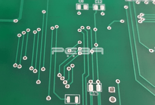
With the miniaturization of mobile devices, high-pitch PCBs must be developed in line with the trend. The reduction in board size to conform to the device size can only be achieved by stacking several layers in a single printed circuit board. These layers do not communicate at the periphery, but through holes known as vias, that can be seen on the PCB. On smaller PCBs however, these vias are rather concealed in plain sight, which can pose a challenge to engineers and technicians who fabricate their own boards.

Vias are not left exposed but covered or filled. For conductivity purposes, copper is preferred when covering or filling the vias, due to its high heat and electrical conductivity. Different designers and manufacturers prefer either method under varying conditions.
When the manufacturer prefers to fill the hole entirely, that via is known as either a filled or masked via. Most designers however prefer covering the surface of the annual ring (the hole), a process called PCB via tenting. BTW, learn more about blind and buried vias here.
What is PCB tenting vias?
As mentioned above tenting vias in PCB is the process of coating the vias' annular ring. Tenting is preferred over the filling, in many cases, as we shall see. During tenting, a solder mask is applied on the surface of the via to limit exposure. If properly done, tenting will protect the via from the elements, as well as reduces the chances of accidental short-circuiting.
Since there aren't specific instructions on how to ensure the hole is shut, you may have mixed results. In some cases, the tenting process will end up covering the hole entirely, but in other cases, the hole remains open. If you are working with smaller vias, typically under 12mil, the probability of having the hole covered is high.
Whether the hole is totally covered or not, there will be a negative effect on the board during assembly, should there be areas on the via not covered by the mask. To avoid this, a dry film solder mask is preferred. It's also easier working with this type of mask.
If SMT pads are to be mounted very close to a via, tenting the latter becomes unavoidable. For those of us familiar with Ball Grid Array (BGA) soldering, you probably do not want a rework underneath the components. You must thus ensure your vias are well tented to avoid any short circuits.
Tenting as a method of covering vias has its advantages and setback. These impacts are manifested on the PCB. If you are seeking to know whether or not to employ tenting or covering, or nothing at all, you must consider your board design first. With that, you can further weigh your option by looking at the positives and negatives of tenting.
Advantages of PCB tenting vias
The most straightforward advantage of tenting is the physical barrier it creates on the via surface. The solder mask applied on the copper traces on the board surface performs the same function. This coat cuts off oxygen and moisture, saving the via from oxidation and thus corrosion. Essentially tenting vias creates a protective physical barrier that can save the connected PCB layers from undue damage.
Once a non-conductive material such as LPI is used in the tenting process, it seals off the conductive tip of the vias that would otherwise be exposed to unforgiving weather conditions. If the vias were not covered, corrosion would take place really fast, degrading the board long before its due time.
Tenting is also critical to reducing possible instances of solder bridging. It's particularly important to carry out proper PCB vias tenting for BGA boards. It might cut down the reworks needed thereafter by more than a half.
Of all other common methods of protecting vias, tenting seems the most affordable. Of course, there are different ways and materials used for protecting the via and the copper on it. These boil down to the varying costs incurred. If you still want to save on the material you use, the Liquid Photo-Imageable solder mask offers you a convenient solution.
Disadvantages of PCB tenting vias
Although a cheap and easy method of protecting vias, tenting has some limitations. These include:
The most cost-effective method of tenting is using an LPI solder mask. This solder mask is usually liquid when applied, and as we all know, liquids occupy lesser volume up on solidification. Due to the stresses set in the LPI layer after drying, cracks usually develop, but at a microscopic level. If the crack is continuously round, that area of the LPI layer may fall off. This exposes the via's surface to the elements such as moisture and chemicals. oxidation and corrosion will thus start, gradually downgrading the PCB.
During the prototyping phase, the vias must be left exposed. This is for the purpose of testing and identifying any issues. The engineer would then be able to address the problems and reroute. If covered, through the tenting process, the engineer will have limited ability to carry out all the necessary testing, thus a problem may be discovered at advanced stages of pcb board manufacture. Needless to say, this could set the schedule back by weeks or even months in massive projects.
Regardless of these challenges, tenting vias is generally an essential part of board manufacture. We explore the importance of this process next.
Why are PCB tenting vias important?
It's arguably one of the commonest practices aimed at protecting a printed circuit board. Compared to filling with epoxy or a mask plugging process, vias tenting very cost-effective. As mentioned above, using a Liquid Photo-Imageable solder mask will cost the least when it comes to vias tenting. To avoid the possibility of the LPI coat peeling you may go for resin filling but obviously at a higher cost.
The primary reason for applying a protective over by tenting is to cover the conductive pads that are not to be attached to any other component. This way, lesser pads are exposed. If there were conditions that would otherwise cause solder bridging, the resin or LPI coat prevents short-circuiting.
Exposed conductive pads increase the possibility of solder migration when the board is being drilled. This problem is more pronounced on SMT pads when working on a standard ball grid array board. Solder migration may also happen if the vias at the SMT pad edges are not covered. The tenting thus protects the vias from solder migration, in addition to cutting off exposure to humidity and oxygen.
The mechanism of tenting a PCB vias requires that the diameter of that via be small. The maximum bore size applicable is 12mil. A diameter larger than this would cause the weight of the liquid resin or LPI to be too high against the surface tension that is supposed to hold the �tent' above the vias. For vias with diameters exceeding 2mil, it's generally advised to consider an alternative such as filling to close the vias. When filling the vias, the conductivity of the material doesn't necessarily matter since the copper plating on the vias conducts sufficiently.
Tenting Vias Vs Plugged Vias
The application of a solder mask over the vias to cover it (tenting vias), can be done in several ways. The most common methods include curtain, screen coating, and spray. In certain conditions, these methods may be insufficient for proper tenting of the vias on all sides. Similarly, screen coating is limited to a certain hole diameter as discussed above, and may also not work for very thick boards.
Plugged vias are mostly the ideal solutions where tenting the vias isn't convenient. A plugged assures that the hole is totally tented and filled. If you settle for a masked via, you will have to ensure that masked plugging has totally sealed and tented the annular ring. At this point, it's rather easy to tell where masked vias can be used. One most common scenario would be when you're doing a ball grid array (BGA) soldering. The close placement of the vias to the SMD pads makes tenting unsuitable.
When plugging a via, the mask clearance must be peeled off the vias by appropriate methods, and the fill is applied into the holes according to the board's design.
Plugged vias can be classified into four types, depending on the material used.
Types of plugged vias
1. Copper filled vias
As the name suggests, these plugged vias are filled with copper metal. The board can thus dissipate heat faster and can conduct a high amount of current. Structurally these vias increase the board's stability, which is necessary for some applications.
2. Conductive and non-conductive material filled vias
Conductively filled vias are generally filled with a metal that conducts just like copper. Apart from what copper offers, these materials come with a challenge- the different thermal expansion rates of the board and the metal. This can result in the board cracking.
Non-conductively filled vias employ a non-conductor as the fill material. This material generally strengthens the board structurally.
3. Solder mask over vias
Here, the solder mask is applied to cover one end of the via or on both ends. Some applications demand that the solder mask be applied only on the annular rings.
4. Copper shut-plated vias
This filling method is mostly applied in high-performance equipment that are expected to withstand rough handling. Military equipment mostly employs this method.
This method requires that a copper plate be placed over the via, enhancing conductivity and reliability over tenting vias.
Conclusion
That's the basic part of PCB tenting vias. By now, you should have decided whether or not to tent your vias. Although the design of the PCB plays a major role in what method you apply, you should generally consider vias larger than 12mils for filling, but smaller diameters can be tented. You can further your argument on the method to use after considering the size of the vias.


