General, quoting & support.
Add: Building E, No.58, Nanchang Road, Xixiang , Baoan District Shenzhen City, Guangdong, China
Tel : 0755-27348887
Fax : 0755-27349876
E-mail : svc@pcbastore.com
What are PCB Test Jigs, PCB Test Fixtures and How to Test PCB?
Byron / 2020-10-27
Contents [hide]
Any electronic project even if properly designed and built with utmost care is prone to bug and issues. It is very crucial to test the product or PCB thoroughly in early stages of design to ensure your projects goes well. The PCB testing can be done at PCB design level after using various design analysis techniques like EMI, Signal Integrity and Power Integrity ,the PCB design issues can be minimized. But how can you test the PCB once bare board PCB is in your hand or after PCB components assembly has been done? How can you make sure that there are no shorts, open or bad solder joints on the PCB? How to make sure current capacity, performance, component value and Impedance are within proper and expected tolerance level? This is exactly what we want to share with you about t how to test PCB with PCB testing jigs/fixtures.
What Is PCB Test Jig and Fixture
It's always good to know and understand the common terms used in the electronics hardware testing business. Generally speaking, a test fixture or test jig is the component containing the bed of nails used for testing the PCB or assembled product. Some PCB test fixtures can be used for edge connector functional testing.
These PCB testing fixtures can either be mechanically or pneumatically operated. The mechanical PCB test fixtures require the user to manually close the test fixture's top hat on the PCB, holding it into place. This activates the bed of nails, pressing it against the PCB. Due to the mechanism involved, the mechanical test fixtures are cheaper in comparison to the pneumatic test fixtures.
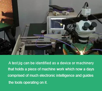
Specialized and custom designed PCB testing jigs and fixtures are used to test PCB. Testing point is identified and probed to identify the input to be given and output to be measured. A PCB testing jig can be identified as a device or machinery that holds a piece of machine work which nowadays comprised of much electronic intelligence and guides the tools operating on it. It should not be confused with PCB testing fixtures which are used to keep the object firmly in place. However, in PCB testing both the terms test jigs and test fixtures are interchangeably used as a electro-mechanical solution to test the printed circuit boards or PCBs. Custom-made PCB test jigs and test fixtures are made as per the application of the board to test its testing points.

Different PCB Testing Ways
1. Bare-board PCB Tests
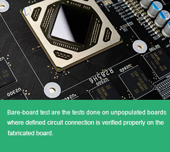
Bare-board PCB test are the tests done on unpopulated boards where defined circuit connection is verified properly on the fabricated board. A small voltage is applied and is verified at the appropriate points, a "short", "open" are identified in these types of tests. Industrial CT scanning can show details of soldered path and connections by generating a 3D rendering of the board along with 2D image slices.

2. Assembly Level PCB Tests
After the board has been properly assembled it may be tested in a variety of ways using either manual inspection or using expensive Automatic Test Equipment (ATE). Automatic test equipment enables PCB test, and equipment test to be undertaken very swiftly. Automatic test equipment is quite expensive, and therefore it is necessary to select the proper type suitable for the application and board to be tested.
3. PCB Functional Tests
Functional test (FCT) is used as a final manufacturing step. It provides a pass/fail determination on finished PCBs before they are shipped. The FCT's purpose in manufacturing is to validate that product hardware is free of defects that could, otherwise, adversely affect the product's correct functioning in a system application.
In short, FCT verifies a PCB's functionality and its behavior. It is important to emphasize that the requirements of a functional test, its development, and procedures vary widely from PCB to PCB and system to system. PCB functional testers typically interface to the PCB under test via its edge connector or a test-probe point. This PCB testing simulates the final electrical environment in which the PCB will be used. The most common form of functional test, known as "hot mock-up" simply verifies that the PCB is functioning properly. More sophisticated PCB functional tests involve cycling the PCB through an exhaustive range of operational tests.
Where to Get Your PCB Testing Jobs Well Done
PCBASTORE Supports a whole set of complete PCB test system (from initial circuit inspection to final function test) to keep your electronics projects going well.
If you have any comments or suggestions about this post, please leave a reply here or contact us, and we will do our best to assist you!
Previous article:Why Choose Multilayer PCB Stackup Planning


