General, quoting & support.
Add: Building E, No.58, Nanchang Road, Xixiang , Baoan District Shenzhen City, Guangdong, China
Tel : 0755-27348887
Fax : 0755-27349876
E-mail : svc@pcbastore.com
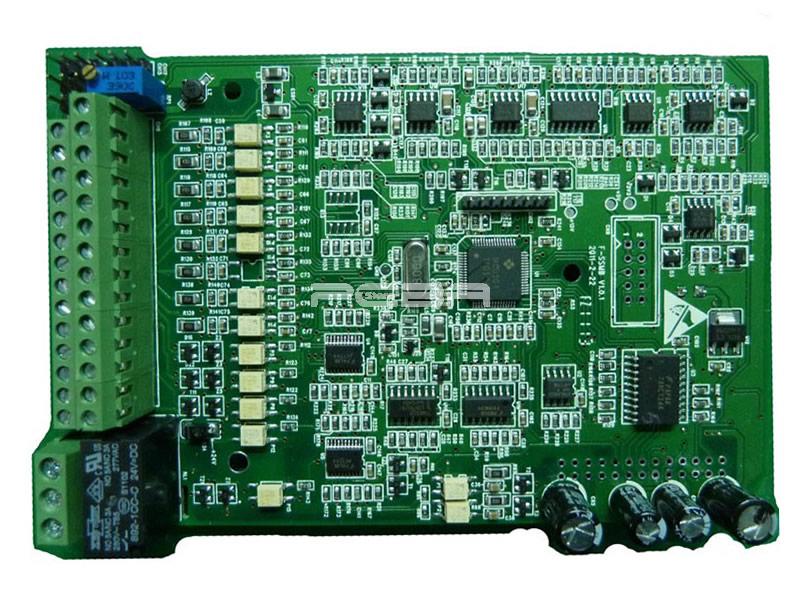
Frequency converter PCBA
Simon / 2021-05-08
Contents [hide]
What is Frequency Converter?
A frequency converter can be best defined as an electrical device that is used to convert the AC of a specific frequency to the AC of a different frequency. These gadgets also fluctuate voltage, but contrary to other gadgets, they are designed to work this way.
Variable frequency, as a technology, had its inception through AC generators. This was also the time when induction motors were introduced to the market. As you switch the speed of your generator you will end up changing its output frequency. And this is exactly the same way the initial models of frequency converter operated.

How Does Frequency Converter Works?
In the following sections, we will take a deeper dive into the technology and the device, shedding more light on its working mechanism, circuit schematics, and more.
How does the Frequency converter device work?
The working mechanism of frequency converters is quite simple. These devices leverage an electrical part called the step-up-transformer. As you would probably guess, this component increases the voltage and ensures that the electrical current moves quickly. In frequency converters, the alternating current passes through a wire coil. You will find a second coil whose electricity is used for powering electrical devices.
Frequency converter circuit schematic
The circuit of a frequency converter is likely to be extremely simple and easy to comprehend. It also comes with plenty of plates. If you are designing the circuit, make sure the copper lines are smaller and narrower. For best results, you should ensure that the copper lining along the capacitors has an extremely short distance to the ground.
Currently, several frequency inverters are used for converting AC to DC and vice versa. You will also find AC-DC-AC variants where the main circuit also functions as the inverter's core circuit. The circuit components here are listed below:
Rectifier: Since it is not quite simple to convert the AC wave in the alternating current mode, your frequency converter's first task would be to convert the incoming electrical wave to DC. The rectifier does exactly this. It transforms AC to DC via a diode bridge that ensures that the AC flows in one specific direction, consistently.
Filter: Filters are used for filtering the ripple voltage from the alternating current. This ripple voltage arises from the direct current and is filtered out before entering the inverter. Several older models of the frequency concerts would need specific line filters for doing the job.
Inverter: The inverter is the brain of a frequency converter. It leverages switching transistors in top speed for creating DC pulses. These pulses again effectively emulate the different phases of the alternating current wave. They also control both the voltage and the frequency of these current waves.
Other components of the frequency converter circuit board include drive, switching power supply, communication, external control, and protection circuits.
Bottom Line
At this point, you probably have a clear idea about the working mechanism of frequency converters. At this stage, you also possibly know how the device controls the motor speed. Almost every leading frequency conversion device allows the user to monitor and manually control the motor speed. This is usually done via switches and keypads. The more modern variants leverage sensors for facilitating the process.
Previous article:Frequency changer power supply PCBA 1500W


